客服电话
0571-63599807

I、Equipment Usage
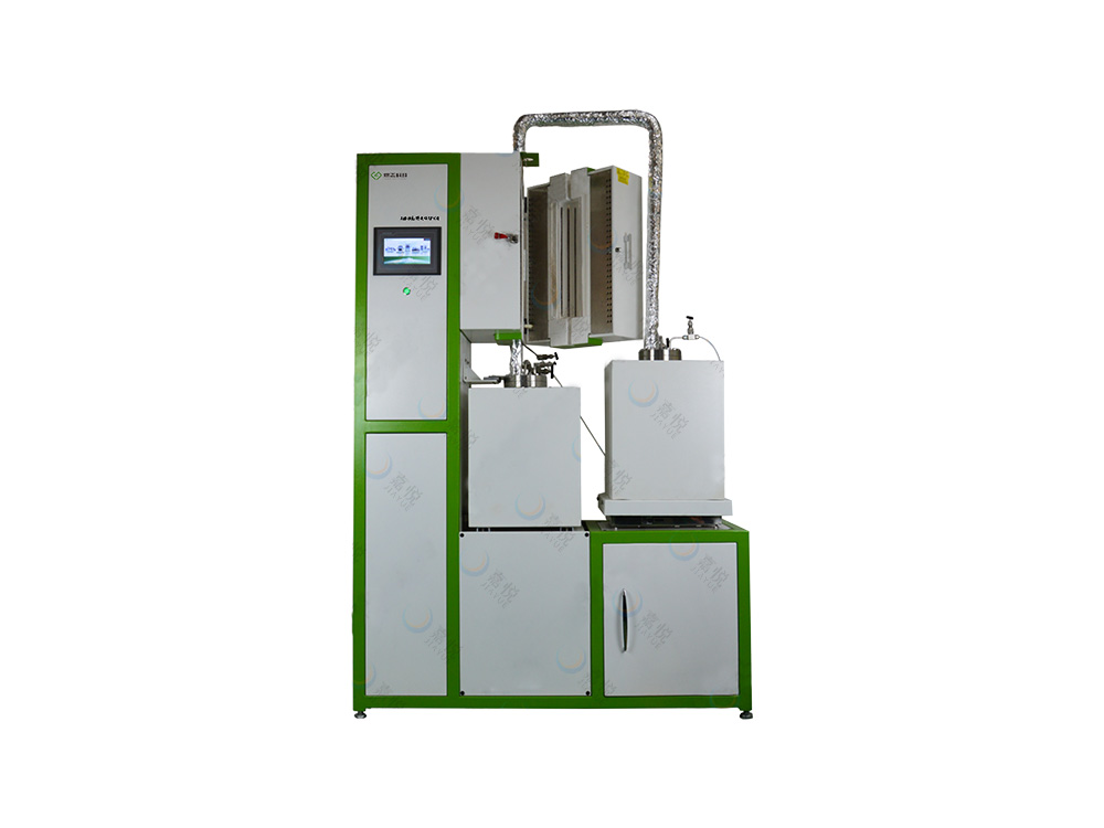
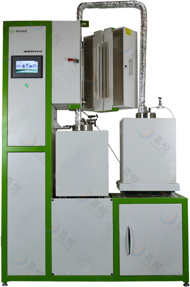
The loop system is mainly used to simulate the operating conditions of the primary and secondary circuits of the reactor and various heat transfer and storage systems. The circulating medium can be heat transfer oil, liquid molten salt or liquid metal, etc. The service verification test, material evaluation test and physical design verification of relevant equipment or components can be carried out.

II、Equipment Introduction
The loop system is composed of high-temperature pump, material storage tank, buffer tank, discharge tank, high-temperature valve, measuring instrument, heat exchanger (if necessary), experimental test unit, heating system, gas circuit system, vacuum system, tail gas treatment system, cooling system, control system, etc. each module is supported by an independent support, which can realize different combinations between modules, facilitating process adjustment and later installation and maintenance.
1. High temperature pump: high temperature pump is a power equipment used to drive the forced circulation of fluid medium. The main design parameters are:
Design temperature: 500 ℃; Flow: < 3m3 / h; Lift: < 15m; Design pressure of pump tank: 0.5MPa.
2. Tank body and pipeline system: the tank body and pipeline are the main structural parts to realize fluid storage and circulation. They can be designed according to actual needs, including material, specification, processing technology and mechanical calculation.
3. High temperature valve: the high temperature valve is made of forged and cast materials resistant to high temperature oxidation and corrosion. It is mainly used to realize the cutoff and flow regulation of high temperature fluid.
4. Measuring instrument: during the loop operation, data acquisition including temperature, pressure, flow and liquid level shall be conducted to obtain the real-time operating conditions of the loop system and ensure the safe operation of the system.
5. Heating system: the heating device shall be designed as required. According to different scales, the covered external heating and the plug-in heating pipe or both can be used respectively. The maximum service temperature of each temperature zone is not higher than 1000 ℃, and the long-term service temperature is recommended to be maintained below 800 ℃. The thermal insulation material is generally aluminum silicate fiber suit customized according to the installation size on site, plus stainless steel shell, which not only ensures good thermal insulation effect, but also looks beautiful.
6. Gas pipeline system: it is composed of gas pipeline, flowmeter, pressure sensor and various valves, which can provide inert atmosphere protection for the system. The pressure and flow range can be designed and adjusted as required.
7. Vacuum system: it is composed of mechanical pump, vacuum valve, vacuum pipeline and vacuum pressure gauge. The maximum limit vacuum can reach 10Pa. The vacuum measuring instrument is a compound digital display vacuum measuring instrument, which can realize continuous vacuum measurement in the whole process.
8. Gas treatment system: the tail gas absorption can be designed in multi-stage series according to the process to absorb or treat the acid-base gas or other harmful gas in the discharged tail gas.
9. Cooling system: the cooling water (deionized water) pumped by the chiller enters the seals or equipment of each branch to be cooled through the main pipe, and then is collected to the water tank. The waterway is equipped with pressure gauge, valve and flowmeter, and the flow can be adjusted as required. It can realize the sound and light alarm of low water pressure, interlock with the control system for protection, and automatically cut off the power supply of the heater.
10. Control system: the control system adopts programmable logic controller (PLC) to realize automatic process control. There are two modes of operation, manual and automatic, which can be selected. The automatic mode can be manually set according to the user's process requirements and equipment requirements, and the interlocking protection design of relevant process parameters is carried out. It is convenient to operate without manual switching. Audible and visual alarms shall be given for abnormal conditions such as over-heating, water shortage, insufficient vacuum, insufficient or too high gas pressure, overload and open circuit of heater, and corresponding protection measures shall be implemented.
III、Product Parameters
|
Type |
Thermal conducting oil circuit system |
Molten salt circuit system |
Liquid metal circuit system |
Nature circuit system |
|
|
Specification |
<400℃-(non-stander design) |
≤700℃-(non standard design) |
≤700℃-(non-stander design) |
≤700℃-(non-stander design) |
|
|
Heating power |
According to design |
According to design |
According to design |
According to design |
|
|
Heating element |
Electric wire |
Electric wire |
Electric wire |
Electric wire |
|
|
Temperature unity |
≤±5℃ |
≤±5℃ |
≤±5℃ |
≤±5℃ |
|
|
Heating rate |
0~15℃ /min |
0~15℃ /min |
0~15℃ /min |
0~15℃ /min |
|
|
Temperature control accuracy |
±1℃ |
±1℃ |
±1℃ |
±1℃ |
|
|
Thermal detected method |
K type thermocouple |
K type thermocouple |
K type thermocouple |
K type thermocouple |
|
|
High temperature pump temperature |
≤500℃ |
≤500℃ |
≤500℃ |
/ |
|
|
High temperature pump rotating speed |
~2900rpm |
~2900rpm |
~2900rpm |
/ |
|
|
High temperature pump moving distance |
≤15m |
≤15m |
≤15m |
/ |
|
|
Medium moving speed |
1-3m/s |
1-3m/s |
1-3m/s |
0.05m/s |
|
|
Storage pressure |
≤0.3Mpa |
≤0.3Mpa |
≤0.3Mpa |
≤0.3Mpa |
|
 浙公网安备33018302001591号ICP备案编号:浙ICP备2022013385号-2